Рекламные объявления:
Продажи от Vasilich: Калькуляторы для iProgGuard и iProgPRO. STool - Программа восстановления одометров. PCMflash - загрузчик для блоков управления двигателем
Внимание всем владельцам iProgGuard, iProgPro, с 01.02.2024 начато обновление ЗИМА 2024. <- Читаем это обязательно. Запуск кальков на Win7(64bit).
MasterEditPro - редактор калибровок ЭБУ
Важная информация по PCMflash, читать обязательно. По оплате STool и PCMflash - читать внимательно, потом не жаловаться


Shapovalov
-
Постов
7652 -
Зарегистрирован
-
Посещение
-
Победитель дней
124
Тип контента
Профили
Форумы
События
Весь контент Shapovalov
-
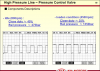
Проверка герметичности сопла Если двигатель автомобиля запускается При работающем двигателе отсоедините форсунки одну за другой. Если отключение одной из форсунок не влечет за собой изменения в работе, это означает наличие неисправности. Замените предположительно неисправную форсунку (относится также к случаю, когда форсунка блокирована в закрытом положении). Удалите из памяти неисправности, вызванные многократными отключениями, и произведите контроль соответствия. Если двигатель не запускается Проверьте уровень и состояние масла в двигателе (на предмет загрязнения топливом). Снимите форсунки, чтобы проверить, нет ли протечек. (Если одно из четырех сопел влажное, в то время как остальные четыре - сухие, то это значит, что форсунка, сопло которой влажное, протекает). Замените неисправную форсунку. Для снятия форсунок, обращайтесь к описанию методики в Руководстве по ремонту. Процедура промывки контура регулировки высокого давления (Только для насоса CP1) Эта операция может привести к поступлению в контур возврата различных частиц, которые могут блокировать или нарушить функционирование регулятора давления. Эти частицы затем оседают в топливном фильтре. Для осуществления этой промывки необходимо подать давление на питающий контур насоса высокого давления и управлять электромагнитным клапаном регулятора давления в топливораспределительной рампе (насос CP1). Подключите диагностический прибор. Войдите в командный режим. Зашунтируйте силовую цепь реле топливного насоса низкого давления на коробке предохранителей защиты цепей двигателя и реле. Начиная с диагностического прибора, подайте команду : Электромагнитный клапан давления топлива" (три-пять раз). Запустите двигатель и произведите замер давления в рампе: Если после проведения операции произошло увеличение давления в рампе: Повторите процедуру промывки, чтобы добиться лучшего результата. Во время последующего дорожного испытания несколько раз полностью нажмите на педаль акселератора, чтобы частицы грязи оказались в баке. Если после проведения операции давление не изменились: Обеспечьте запуск топливного контура низкого давления (низкое давление в пределах 2,5-4 бар). Проверьте отсутствие утечек в контуре высокого давления. Проверьте состояние топливного фильтра (измерение производительности на входе и выходе). Проверьте герметичность контура высокого давления: насос, трубопроводы, штуцеры. Убедитесь в надежности работы форсунок (в отсутствии внутренних протечек в контуре возврата, в их чистоте, в отсутствии заеданий: см. диагностику форсунок). Проверьте надежность работы датчика давления. Если все проверки дали положительный результат, замените регулятор давления.
-
Может сам датчик t или указатель в приборке ? Сканер подключи.
-
В Аллдате ничего кроме этого:4. CONNECT CABLE TO NEGATIVE BATTERY TERMINAL 5. ADD AUTOMATIC TRANSAXLE FLUID 6. INSPECT AUTOMATIC TRANSAXLE FLUID 7. INSTALL NO. 2 ENGINE UNDER COVER (w/No. 2 engine under cover) 8. INSTALL NO. 1 ENGINE UNDER COVER 9. INSTALL ENGINE UNDER COVER ASSEMBLY (w/engine under cover assembly) 10. RESET MEMORY 11. PERFORM INITIALIZATION 2007 Lexus Truck RX 350 FWD V6-3.5L (2GR-FE) Copyright © 2009, ALLDATA 9.90 Page 2 HINT: Some systems need initialization after reconnecting the cable to the negative battery terminal. Ну обороты ХХ адаптировать.
-
Первый раз слышу о сбросе сервиса на Грандах.Жёлтая надпись на приборке со словом Servis и т.д. - означает наличие ошибок в моторнике и АКПП.Если нет чем диагностить,то три раза вкл.и выкл. зажигание(последний раз вкл.)и на месте одометра высветит "Р" коды."Done" - это конец сообщения или нет ошибок. P.S.Над зеркалом заднего вида есть разные функции,но они и сбрасываются там-же.
-
Будет постов 20 одних допросов: "какой год,а насос лукас"...? Напиши сам,цвет авто и имя владельца не понадобится.
-

-
Коммон ВАГTDI.doc Вот ещё,может сгодится...http://wiki.audi-bel.com/wiki/%D0%9F%D1%80%D0%B8%D0%BD%D1%83%D0%B4%D0%B8%D1%82%D0%B5%D0%BB%D1%8C%D0%BD%D0%B0%D1%8F_%D1%80%D0%B5%D0%B3%D0%B5%D0%BD%D0%B5%D1%80%D0%B0%D1%86%D0%B0%D1%8F_%D1%81%D0%B0%D0%B6%D0%B5%D0%B2%D0%BE%D0%B3%D0%BE_%D1%84%D0%B8%D0%BB%D1%8C%D1%82%D1%80%D0%B0
-
В эльзе написано всё(или "подсказку" открыть).Вот про форсунки где и как смотреть. Customer statement / workshop findings White smoke from the exhaust system and juddering when the engine runs at idle speed for some time - V6 TDI 2.7l / 3.0l TDI. Technical background Mechanical wear of the needle attachment of the injector leads to an increased fuel injection into the combustion chamber. The fuel is not completely burnt, which causes white smoke (unburnt fuel) or juddering when the engine runs at idle speed for some time. This complaint occurs only on vehicles with more than 50,000 km. Production change Modified injectors from: 8E47A040360 4F37N026750 4EX7N004204 4L*7D049162 Measure Try to reproduce the customer complaint so that it can be clearly assigned to this TPI. The following repair must only be carried out, if all the criteria (model/type, chassis number, engine/gearbox code, PR number(s), software version, code etc. ) match exactly. Otherwise this solution won't work and repeat repairs may be necessary. In such a case, we may reject the warranty claim and redebit the parts. Read the measured value blocks 72 - 77. 3 values per measured value block appear there (for 300 bar, 600 bar, 1000 bar). Should the values be higher than minus -45 ms (example - 60ms) or on digit 2 be higher than minus -15 ms (e.g. 20ms), the needle attachment is worn and the injector is incorrect. To avoid repeat repairs, replace all 6 injectors. >>>> Observe the algebraic sign (minus) in measured value block 72-77 !!!!! <<<<< Warranty accounting instructions Service number/damage code/manufacturer: 2340/010
-
Всё в тему,о том ,что без сканера искать причину...Что даже датчик обучать надобно.
-
2007 Hummer H3 L5-3.7L Copyright © 2009, ALLDATA 9.90 Page 1 Crankshaft Position Sensor: Procedures Crankshaft Position System Variation Learn Important: The crankshaft position (CKP) system variation learn procedure is required when the following service procedures have been performed, regardless of whether DTC P0315 is set: * Engine replacement * ECM replacement * ECM reprogramming * Crankshaft damper replacement * Crankshaft replacement * CKP sensor replacement * Any engine repairs which disturb the crankshaft to CKP sensor relationship Important: The scan tool monitors certain component signals to determine if all the conditions are met to continue with the CKP system variation learn procedure. The scan tool only displays the condition that inhibits the procedure. The scan tool monitors the following components: * CKP sensor activity-If there is a CKP sensor condition, refer to the applicable DTC that set. * Camshaft position (CMP) signal activity-If there is a CMP signal condition, refer to the applicable DTC that set. * Engine coolant temperature (ECT)-If the engine coolant temperature is not warm enough, idle the engine until the engine coolant temperature reaches the correct temperature. 1. Install a scan tool. 2. Monitor the engine control module (ECM) for DTCs with a scan tool. If other DTCs are set, except DTC P0315, Refer to Diagnostic Trouble Code (DTC) List - Vehicle for the applicable DTC that set. See: Computers and Control Systems/Testing and Inspection/Diagnostic Trouble Code Descriptions/Diagnostic Trouble Code (DTC) List - Vehicle 3. With a scan tool, select the CKP system variation learn procedure within the Special Functions menu and perform the following: 1. Observe the fuel cut-off for the applicable engine. 2. Block the drive wheels. 3. Set the parking brake. 4. Place the vehicle's transmission in Park or Neutral. 5. Turn the air conditioning (A/C) OFF. 6. Cycle the ignition from OFF to ON. 7. Apply and hold the brake pedal for the duration of the procedure. 8. Start and idle the engine. 9. Accelerate to wide open throttle (WOT). The engine should not accelerate beyond the calibrated fuel cut-off RPM value noted in step 3.1. Release the throttle immediately if the value is exceeded. Important: While the learn procedure is in progress, release the throttle immediately when the engine starts to decelerate. The engine control is returned to the operator and the engine responds to throttle position after the learn procedure is complete. 10. Release the throttle when fuel cut-off occurs. 4. The scan tool displays Learn Status: Learned this Ignition. If the scan tool indicates that DTC P0315 ran and passed, the CKP variation learn procedure is complete. If the scan tool indicates DTC P0315 failed or did not run, Refer to DTC P0315. If any other DTCs set, Refer to Diagnostic Trouble Code (DTC) List - Vehicle for the applicable DTC that set. See: Computers and Control Systems/Testing and Inspection/Diagnostic Trouble Code Tests and Associated Procedures/P Code Charts/P0315 See: Computers and Control Systems/Testing and Inspection/Diagnostic Trouble Code Descriptions/Diagnostic Trouble Code (DTC) List - Vehicle 5. Turn OFF the ignition for 30 seconds after the learn procedure is completed successfully.
-
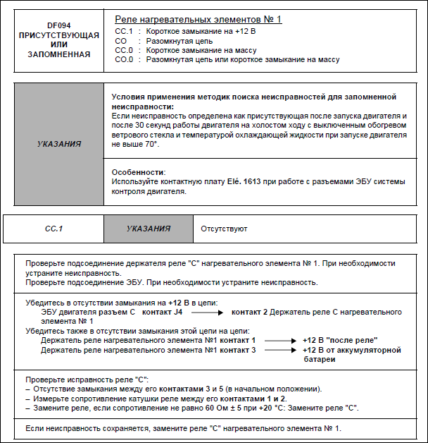
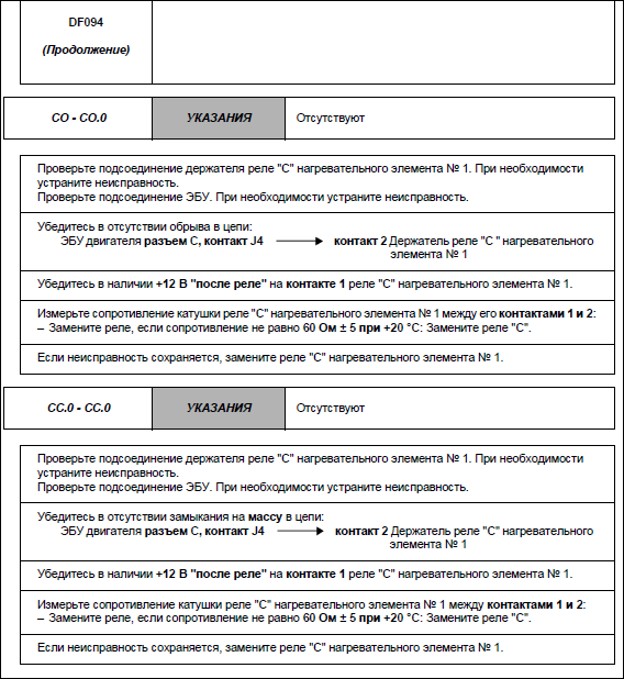
Первую страницу ошибки 094 в запарке не отправил.
-
Санёк,а чем ты её диагностишь(или какой V)? "P242F" - такое не встречалось? "Готовность" что показывает? И в канале форсунок какие показания?
-
Спасибо,успокоил!Уже не верю в "просто решаемые" поломки на ВАГовской группе,последнее время - одни головоломки.Спасибо!
-
Antilock Brakes / Traction Control Systems: Testing and Inspection Procedures ABS/ESP ITT Mark 20/60 Basic Setting (function 04) The "Initiating Basic Setting" function 04 does the following for ESP: Display group number 001 is only necessary for bleeding the hydraulic unit. In display group number 031, a functional test is performed for the magnetic coil for brake pressure and for the magnetic coil for brake recognition. Display group number 040 is required for shutting off the longitudinal acceleration sensor -G251-, e.g. for checking the brake system on a rolling dynamometer.1) Display group numbers 060, 063 and 066 are required for zeroing the steering angle sensor, the lateral acceleration sensor and the sensor for brake pressure. Display group number 069 is required for zeroing the longitudinal acceleration sensor -G251- 1). 1) Only for All Wheel Drive (AWD) vehicles with Haldex coupling The hydraulic unit is bled via display group 1 for vehicles with the ESP system. Initiate basic setting. Basic setting 04 display group number 1 is required if at least one chamber of the brake fluid reservoir has been emptied completely. Also perform basic setting after repairing leaks in the brake system. Function 11 "Login-Procedure" is not necessary in this case. A function test of the magnetic coil for brake pressure and the switch for brake recognition is performed via display group number 31. This is necessary if: - Brake booster is replaced. - DTC memory requests it. Function 11 "Login-Procedure" is not necessary in this case. The longitudinal acceleration sensor -G251- is switched off via display group 40 This is only necessary for All Wheel Drive vehicles with Haldex couplings. Zeroing procedures can be performed via display group numbers 60, 63 and 66. The steering angle sensor -G85- is zeroed using display group 60. The sensor for transverse acceleration is zeroed via display group 63. The sensor for brake pressure is zeroed via display group 66. Before zeroing via display group numbers 60, 63 and 66, "Login-Procedure" function 11 must first be carried out successfully using the VAG1551/1552 scan tool for ABS/EDL/ASR/ESP This is necessary if: - The ABS control module -J104-, the steering angle sensor -G85-, or the steering column is being replaced. - The steering angle sensor -G85- is being replaced. - Adjustments are made to the suspension during a vehicle alignment. - If steering wheel was removed, perform a zeroing in display group number 60. - The sensor for transverse acceleration -G200- is being replaced. - The sender 1 for brake booster -G201- and / or sensor -2- for brake pressure -G214- are being replaced. - If the DTC table instructs you to zero the sensor based on a DTC in DTC memory of the ABS control module -J104-. The longitudinal acceleration sensor -G251- is zeroed via display group 069. This is only necessary for All Wheel Drive vehicles with Haldex couplings.
-
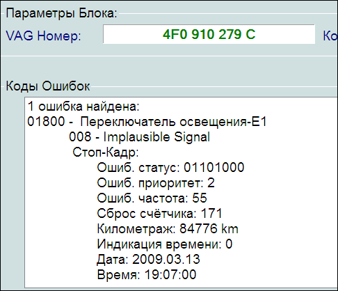
Не могу найти инфу по этой ошибке.Вина переключателя Е1,или всё-таки кодировками исправлять надо?Владелец говорит,что раньше свет не горел (при запуске мотора).После ремонта света фар это стало.Где ремонтировал не признаётся.Прошу помощи!!!
-
Computers and Control Systems: Component Tests and General Diagnostics Engine Speed (RPM) Sensor, Checking Engine Speed (RPM) Sensor, Checking Function The Engine Speed (RPM) Sensor -G28- detects engine speed and reference marks. Without an engine speed signal, the engine will not start. If the engine speed signal fails while the engine is running, the engine will stop immediately. Recommended special tools and equipment - V.A.G 1526 multimeter or V.A.G 1715 multimeter - V.A.G 1594 connector test kit - Wiring diagram Test requirements - Ground (GND) connections between engine and chassis must be OK. - Ignition switched off. Test sequence - Disconnect gray 3-pin harness connector (arrow) to Engine Speed (RPM) Sensor -G28-. - Measure sensor resistance between terminals 2 + 3 at connector to sensor. Specified value: 480 to 1000 Ohms - Check sensor for short circuit between terminals 1 + 2 as well as 1 + 3. Specified value: infinite Ohms If specified values are obtained: - Check wiring. If specified values are not obtained: - Replace Engine Speed (RPM) Sensor -G28-. - Erase DTC memory of Engine Control Module (ECM), Diagnostic mode 4: Reset/erase diagnostic data. See: Scan Tool Testing and Procedures/With Generic Scan Tool/Diagnostic Mode 4: Reset/Erase Diagnostic Data - Generate readiness code. Checking wiring - Connect test box to control module wiring harness, connect test box for wiring test. See: Reading and Clearing Diagnostic Trouble Codes/Scan Tool Connecting/Test Box, Connecting For Wiring Test - Check wires between test box and 3-pin connector for open circuit according to wiring diagram. Terminal 1 + socket 108 Terminal 2 + socket 90 Terminal 3 + socket 82 Wire resistance: max. 1.5 Ohms - Also check wires for short circuit to each other. Specified value: infinite Ohms If no malfunctions are found in wires: - Remove sensor and check sensor wheel for secure fit, damage, and run-out. NOTE: There is a larger-sized gap on the sensor wheel. This gap is the reference mark and does not mean that the sensor wheel is damaged. If nothing seems to be wrong with the sensor wheel: - Replace Motronic Engine Control Module (ECM) -J220-.

-
-
P1560 - Cruise Control - Transmission not in Drive P1560 - Transaxle Not in Drive - Cruise Control Disabled Это с разных ресурсов.Проверь круиз.
-
Считывание кодов диагностики электронных систем упр.doc
-

-
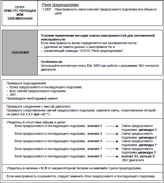
Свечи 1 и 3 цилиндра и катушки лучше-бы проверил. Впрочем,каждый сам выбирает себе "Ивана Сусанина".
-
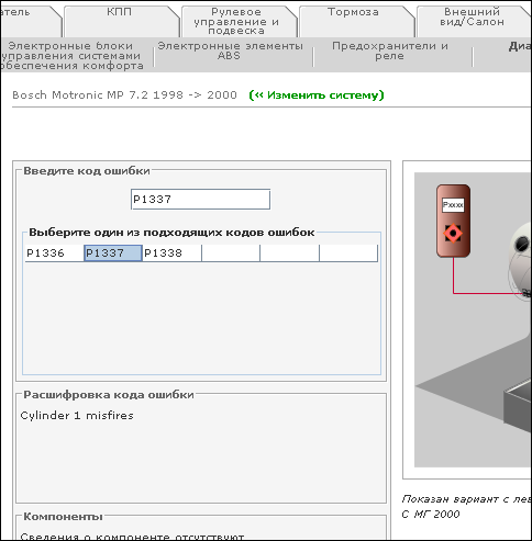
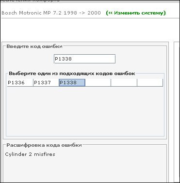
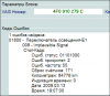
1336 - множественные пропуски по цилиндрам. 1337 - 1 цилиндр. 1338 - 2 цилиндр. и т.д. Утверждать не буду,лягушатину не ем.
-
1996 BMW 750iL (E38) V12-5379cc 5.4L SOHC (M73) Copyright © 2009, ALLDATA 9.90 Page 1 Idle Speed/Throttle Actuator - Electronic: All Technical Service Bulletins Section C: Defect Code 00 13 04 01 00 and 00 12 08 01 00 (Resetting EML Adaptation Values on all affected vehicles if a component(s) was replaced) 1. Reconnect battery, connect DIS and turn ignition to the on position (engine not running). 2. Select "Engine Power Control". 3. Select "3 Service Functions". 4. Select "5 Reset adaptation values". 5. Select "1 Pedal travel sensor adaptation values". Page back <- 6. Select "2 Throttle valve adaptation values". Page back <- 7. Select "3 Cylinder bank synchronization". Page back <- Page back <- 8. Select "1 Execute basic pedal-travel-sensor adaptation". Follow the instructions given in order to adapt PWG sensor. NOTE: It is important that the accelerator pedal be fully depressed when "kickdown end position" is requested otherwise the status values will not go beyond status 3. If status 5 is not reached, turn the ignition off for at least 10 seconds to allow the system to reset. The status value must be at 1 after the ignition is turned to the on position, in order to allow the adaptation process to be repeated. Continue to reset the system and repeat the adaptation process until status 5 is reached. Once status 5 is reached with accelerator not depressed turn the ignition off for 10 seconds. The status value must be at 0 after the ignition is turned to the "on" position, otherwise the adaptation process must be repeated. 9. Once throttle response has been verified with engine running - clear all faults set in the EML control module.
-
Заказал термостат и крышку бачка расширительного.Вчера вечером поменяли и заодно эл.заслонки почистили.Гонял весь день и не глушил с утра - всё нормально !!! С адаптацией заслонок пришлось попотеть.КТС не связался ни с каким блоком (а заявленно!).Раза с 25го прошла адаптация "педальным способом" и с секундомером.Обороты плавали с 1200 - 1500. Всем откликнувшимся СПАСИБО !
-
1.Из 4 обратившихся на ремонт,закончилось заменой блока.А было только 4 машины таких. 2.Приглашал знакомого (ливанца) со "Снапоном" и он вбивал данные шасси.